
When a manual assembly stage is used in manufacturing, it is essential to assembe the correct parts of the product in the right order. Using the wrong part – for example, the wrong type of screw, or the wrong plastic attachment – could result in the end product failing quality assurance tests.
You can proactively address this risk by introducing an automated manual assembly QA step using computer vision. You can use a camera to monitor what parts are selected, then use computer vision to ensure the correct parts are chosen in the right order. This could be accompanied with an interactive instruction system so an assembler knows what part to pick next. If the wrong part is selected, a warning can be displayed.
In this guide, we are going to walk through how to build a manual assembly QA system. We will train a system that can identify and distinguish between three separate parts. We will then build logic that ensures the correct parts are chosen by an assembler during the manufacturing process.
Here is an example of our system running with the example of Lego blocks:
In this system, we advise the assembler on what part to pick up next. When the wrong part is selected, an error is displayed. When assembly is complete, a notification appears indicating this status so the person handling manufacturing knows to move on to assemble the next product.
Without further ado, let’s get started!
Step #1: Collect and Upload Data
Create a free Roboflow account, then click the “Create a Project” button on your Roboflow dashboard. You will be taken to a page where you can configure your computer vision project. On this page, choose a name for your project. Then, click “Object Detection” as the project type.
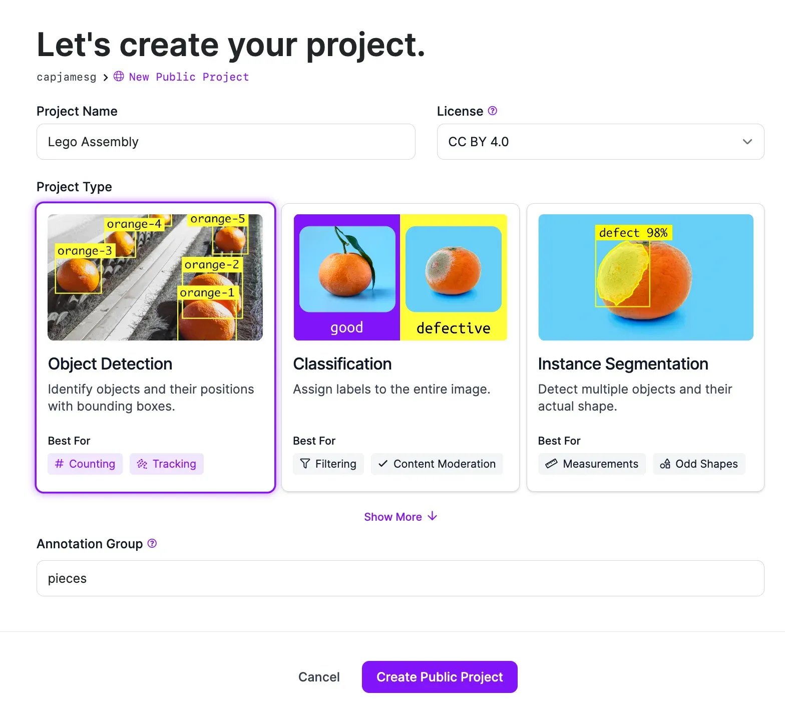
When you have filled out all the fields on the page, click “Create Project”. Your project will be created and you will be taken to a page where you can upload your images.
Step #2: Upload Data
To build a vision system, we need to collect images of the parts we want to be able to identify. We will later annotate these images to help our model learn to distinguish between different parts
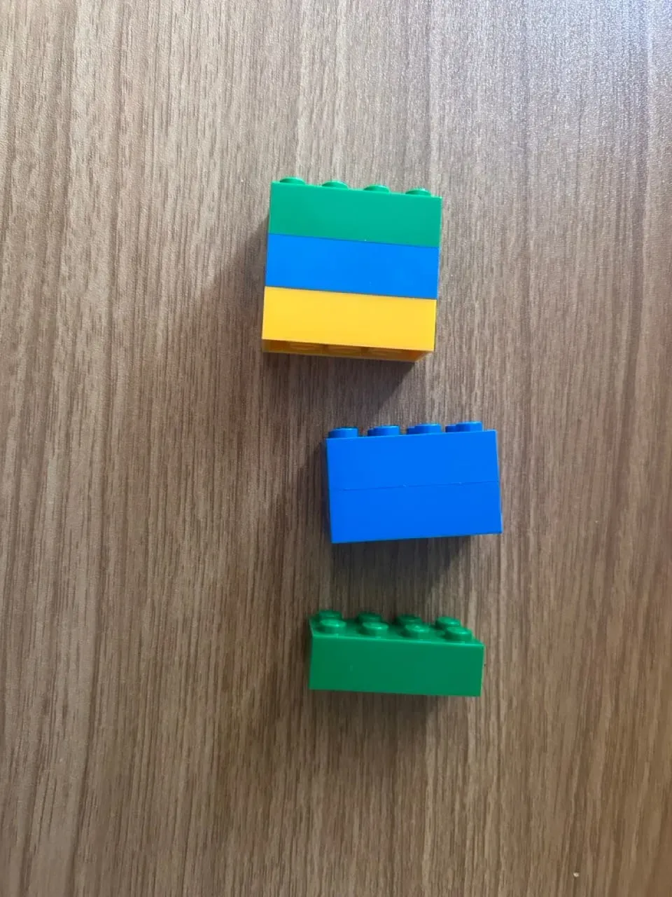
You should collect images of the exact parts you are using. In this example, we will collect images of three separate Lego block types: blue, orange, and green 4x2 blocks.
You should aim to collect 20-50 images of parts at different orientations so that the system can track the part even if it is being handled at different angles. This system will perform best when parts are sufficiently different. For example, if two screws are almost identical other than in size, the system may struggle to differentiate between them.
Once you have collected images of your parts, you can upload them to Roboflow for use in building your vision model.
To upload your images, drag and drop them into the Roboflow upload data page to which you were taken after creating your project.
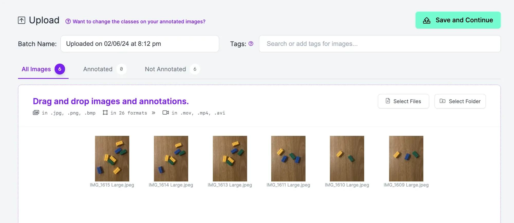
When your images have been processed, click “Save and Continue” to upload your data.
Step #2: Label Data
Computer vision systems need labeled images to learn how to identify different objects. You can label, or annotate, your images in Roboflow for use in training a model. Labeling data for an object detection project like this one involves drawing boxes around all objects of interest. These boxes will be used by the system to learn the properties of different objects.
To start labeling data, click Annotate in the left sidebar of your project. Then, click on an image to annotate. You will be taken to the Roboflow Annotate interface in which you can label your data.
To start labeling an image, press “b” on your keyboard or select the box tool in the left sidebar. This will select the bounding box annotation tool. Draw a box as close to the edges of the objects you want to label as possible. Your box should contain the whole object of interest.
Once you draw a box around the object, you will be asked to select a label. Your class names should be descriptive. For example, if we were labeling a yellow Lego block, we could set the label Yellow 4x2 Block. We would then label all yellow blocks in all our images with that same label.
Label all images in your dataset.
Step #4: Generate a Dataset Version
With all your images labeled, you are ready to generate a dataset version. A dataset version is a frozen-in-time version of your dataset that you can use to train a vision model. In Roboflow, you can apply preprocessing steps to prepare your images for model training at this stage. You can also generate augmented images which may help boost model performance.
To generate a model version, click “Generate” in the left sidebar. You will be taken to a page on which you can configure your dataset. We recommend leaving all preprocessing steps as their defaults. For augmentations, we recommend applying a rotate augmentation. This will ensure parts are identified no matter at what angle a piece is held.
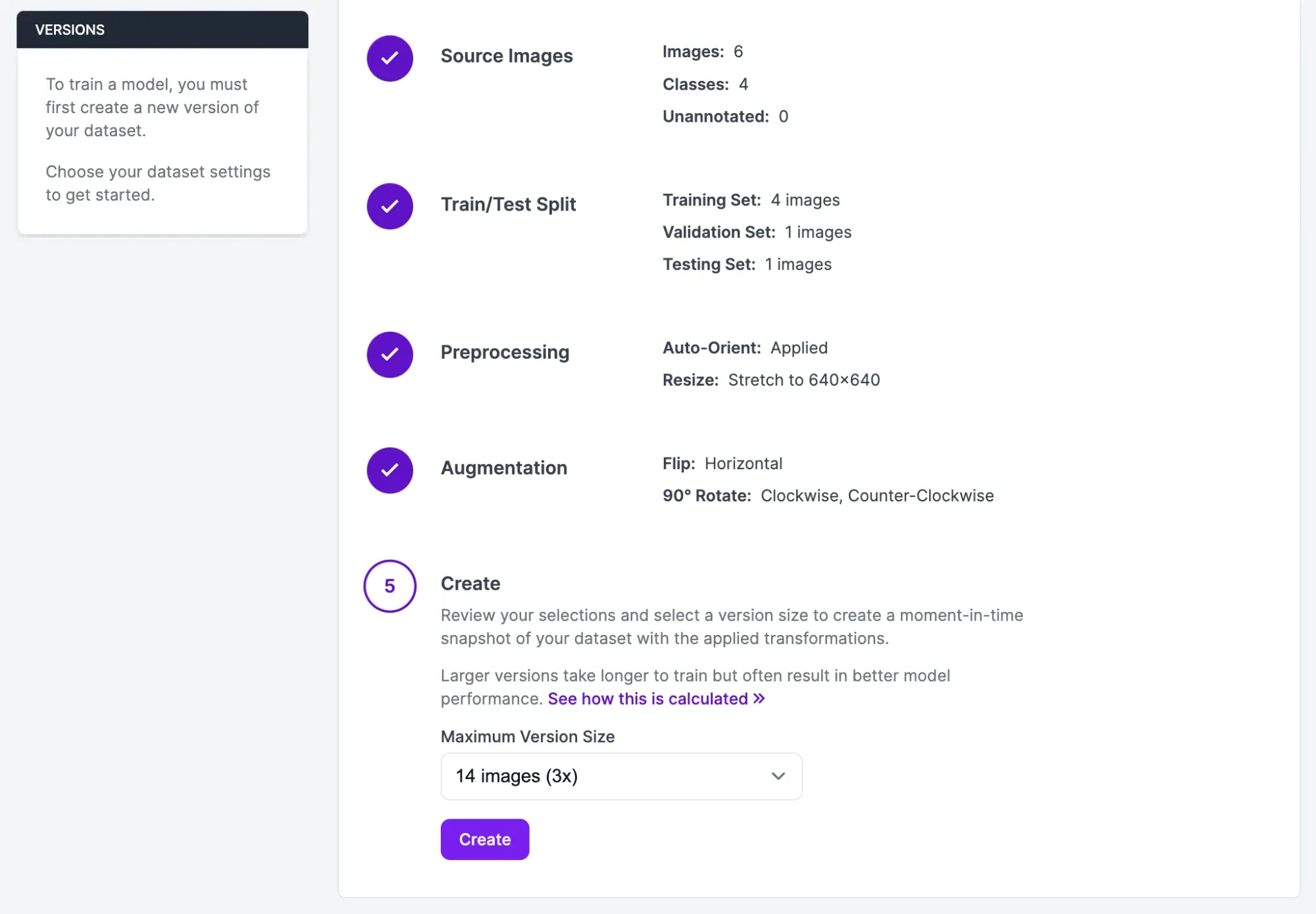
Once you have applied this augmentation, scroll down to the last step on the page and click the “Create” button. Your dataset version will be generated. This may take a few moments.
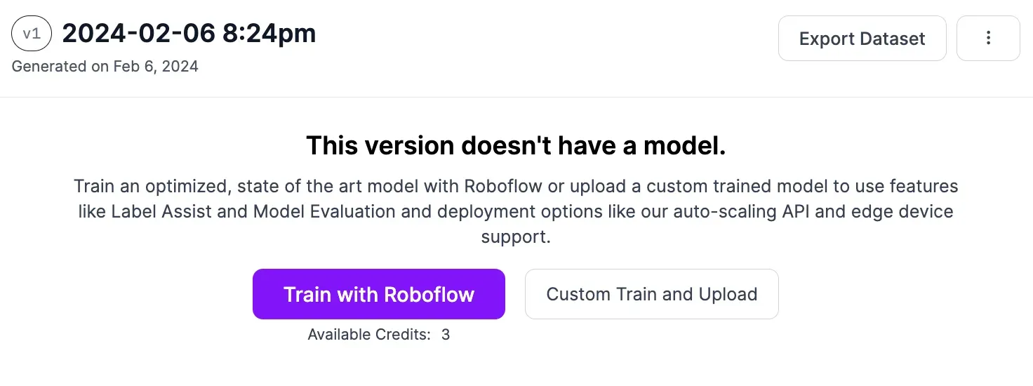
You will be taken to a page where you can start training your vision model.
Step #5: Train a Model
With a dataset ready, you can now train a vision model to identify the part types you labeled earlier in this guide. We will use this vision model with some logic that we write later in this guide to build our manual assembly QA system.
To start training a model, click the “Train with Roboflow” button. When prompted, select the Fast training option. Then, select the option to train from a public checkpoint. Make sure Microsoft COCO is selected as the checkpoint from which to train.
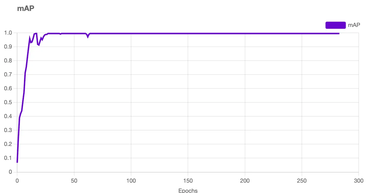
After you have configured your model training job, model training will begin. You will receive an estimate of how long it should take to train your model.
You can monitor the live progress of your training job. A graph will appear when your model starts training that shows the performance of your model as it trains.
Once your model has finished training, you can test it from the “Visualize” page, accessible by clicking “Visualize” in the left sidebar of your project page.
Here is an example of our model working to identify different Lego pieces:
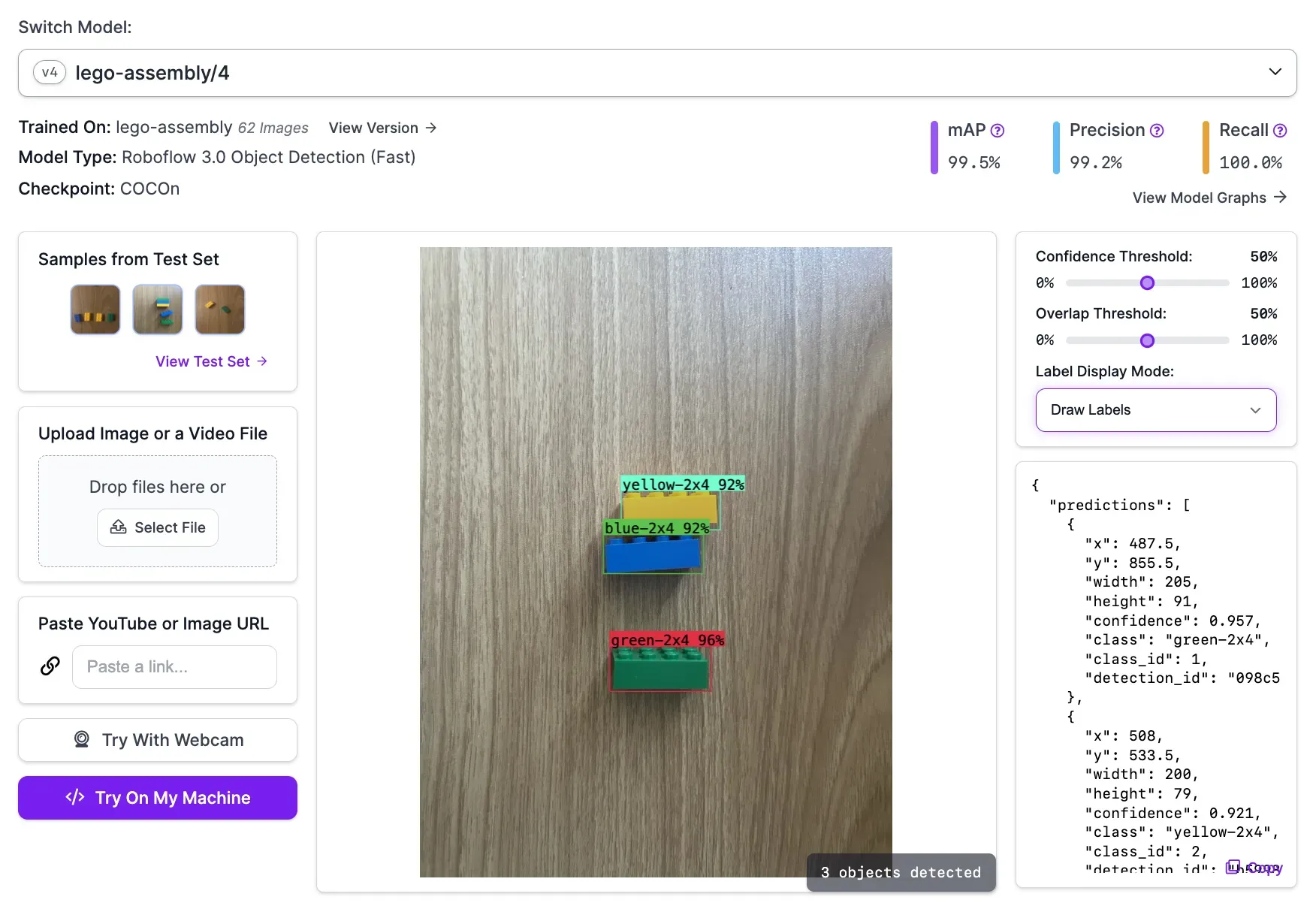
Our model successfully identified all Lego pieces.
Step #6: Use the Model for Manual Assembly QA
The vision model we have trained allows us to identify different parts. With this model, we can write logic that ensures the correct parts are picked up in the correct order. To do this, we will use Python with a few packages.
We will use Inference to run our vision model on our own hardware. This is optimal for manual assembly where close-to-real-time performance is essential.
We will use supervision to track objects as they become visible, show what objects are present, and display a message that indicates the next part to pick up (or shows a warning if an assembler picks up the wrong part).
To install Inference and supervision, run the following command in a programming terminal:
pip install inference supervisionWith supervision installed, we can start writing our logic.
Create a new Python file and add the following code:
import optparse

import cv2
from inference import InferencePipeline

import supervision as sv

parser = optparse.OptionParser()

parser.add_option(
    "-o", "--order", action="store", dest="order", help="Order of parts to be assembled"
)
parser.add_option("-m", "--model_id", action="store", dest="model_id", help="Model ID")
parser.add_option(
    "-v",
    "--video",
    action="store",
    dest="video",
    help="Specify a camera ID or video file on which to run inference",
)
parser.add_option(
    "-c", "--classes", action="store", dest="classes", help="Classes of the model"
)

args = parser.parse_args()[0]

if not any([args.order, args.model_id, args.video, args.classes]):
    parser.error("Missing required arguments")

order = [i.strip() for i in args.order.split(",")]

tracked_ids = set({})
current_step = 0
active_parts_not_in_place = set({})
last_detection_was_wrong = False
classes = [i.strip() for i in args.classes.split(",")]
complete = False

tracker = sv.ByteTrack()
smoother = sv.DetectionsSmoother()
In this code, we import the packages we are using. We then set a few arguments that we can pass into our script when we run it:
--order: The order in which objects should be assembled.--model_id: Our Roboflow model ID.--video: The video file or camera stream on which we want to run inference.--classes: The classes supported by our model, ordered by how they appear in the Roboflow dashboard.
We then set up our object tracker and smoother. We will use the tracker to monitor where objects are in our video at a given time. We will use the smoother to improve accuracy of our system.
Add the following code to your script:
def on_prediction(inference_results, frame):
    global current_step
    global last_detection_was_wrong
    global complete

    predictions = sv.Detections.from_inference(inference_results).with_nms()
    predictions = tracker.update_with_detections(predictions)
    predictions = smoother.update_with_detections(predictions)

    predictions = predictions[predictions.confidence > 0.85]

    message = (
        f"Wrong part! Expected {order[current_step]}"
        if len(active_parts_not_in_place) > 0
        else None
    )

    for prediction in predictions:
        if prediction[4] in tracked_ids:
            continue

        class_name = classes[int(prediction[3])]

        if class_name == order[current_step]:
            tracked_ids.add(prediction[4])

            print(f"Part {class_name} in place")
            if current_step == len(order) - 1:
                print("Assembly complete!")
                complete = True
                break

            current_step = current_step + 1
            active_parts_not_in_place.clear()
            break
        elif class_name == order[current_step - 1]:
            tracked_ids.add(prediction[4])
            last_detection_was_wrong = False
            active_parts_not_in_place.clear()
        else:
            active_parts_not_in_place.add(prediction[4])
            last_detection_was_wrong = True

    bounding_box_annotator = sv.BoundingBoxAnnotator()
    label_annotator = sv.LabelAnnotator()

    text_anchor = sv.Point(x=700, y=100)

    if complete:
        message = "Assembly complete!"

    next_step = f"Next part: {order[current_step]}" if message is None else message

    annotated_image = bounding_box_annotator.annotate(
        scene=frame.image, detections=predictions
    )
    annotated_image = label_annotator.annotate(
        scene=annotated_image,
        detections=predictions,
        labels=[classes[int(i[3])] for i in predictions],
    )
    annotated_image = sv.draw_text(
        scene=annotated_image,
        text=next_step,
        text_anchor=text_anchor,
        text_scale=2,
        background_color=sv.Color(r=255, g=255, b=255),
        text_color=sv.Color(r=0, g=0, b=0),
    )

    cv2.imshow("Inference", annotated_image)
    cv2.waitKey(1)
Let’s talk through this code step by step.
First, we run the results of our model (the “predictions”) through our tracker and smoother. We run through each new prediction to see what objects have entered view. If the correct part is selected, the script advances to the next stage defined in the order variable earlier.
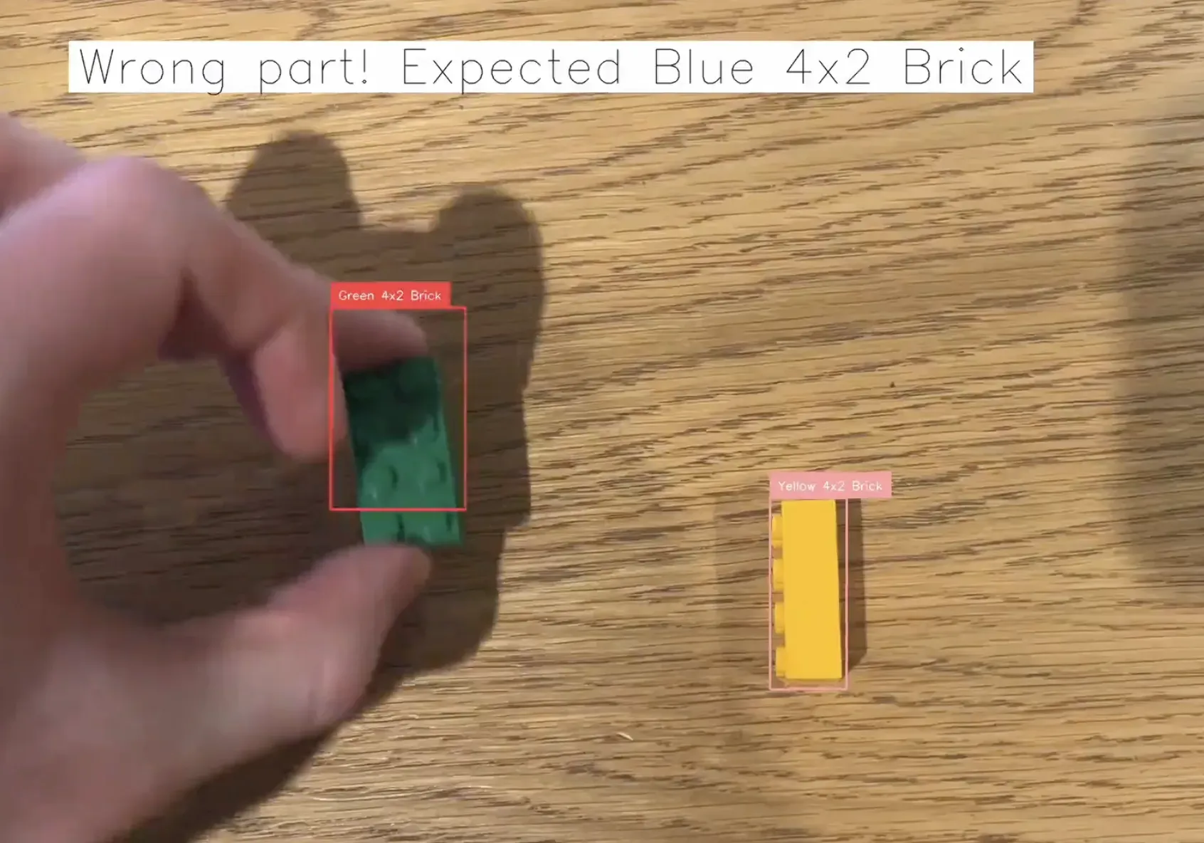
If the wrong part is selected, a warning message will appear that informs the assembler that they should put the part they are holding back and select the correct one.
For example, if a green brick comes into view when a blue one was expected, our script will inform the assembler that the next step is to pick up a blue brick.
We keep track of whether the last part selected was incorrect to ensure this can be referenced across subsequent frames in a live feed until the correct object is selected
We use the supervision annotation features to visualize the results of our manual assembly live on our video feed. We use the OpenCV Python package to show the results on screen.
We have now written the logic to ensure the correct parts are picked up. There is one missing piece: running our model and logic on a live video feed. For this task, we will use the InferencePipeline class offered in Inference. This class allows you to run a vision model and a custom callback function – such as the on_prediction function we made earlier – on all frames in a live feed.
Add the following code to your script:
pipeline = InferencePipeline.init(
    model_id=args.model_id,
    video_reference=args.video,
    on_prediction=on_prediction
)

pipeline.start()

pipeline.join()
The value of video_reference informs the script what camera to use. To use your default camera, set the value to 0. You can also specify an RTSP stream. For testing, you can specify the name of a video. This is ideal for use in refining the logic for your script.
Let’s try to assemble Lego pieces according to the order we specified in our script:
- Yellow 4x2 Brick
- Blue 4x2 Brick
- Green 4x2 Brick
Before we run our script, we need to set our Roboflow API key in an environment variable called ROBOFLOW_API_KEY:
export ROBOFLOW_API_KEY="key"Learn how to retrieve your Roboflow API key.
Now we can run our script like so:
python3 app.py -o "Yellow 4x2 Brick, Blue 4x2 Brick, Green 4x2 Brick" -v 0 -m "lego-assembly/4" -c "Blue 4x2 Brick, Green 4x2 Brick, Yellow 4x2 Brick"The command consists of the following parts:
-o: The assembly order you want to enforce (i.e. yellow brick first, then blue brick).-v: The webcam or video we want to use.0is the default webcam on your system.-m: The model we want to run. Learn how to retrieve your model ID.-c: The classes our model supports.
The value you provide for the classes (-c) argument should be in the same order as they appear on the "Classes" page in your Roboflow project:
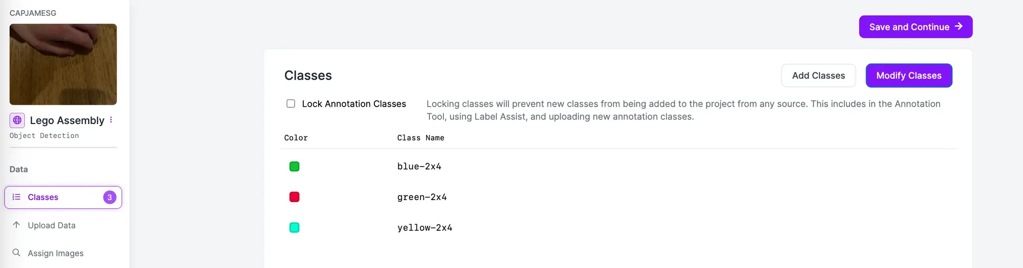
Here are the results:
When we select the yellow brick, our script informs us the next brick to pick up is a blue brick. We tried to pick up a green brick and use it in assembly when using a blue brick was specified as the next step. Our script warned us that we had picked up the wrong part. When we selected the correct part, we were able to move on to the final step: adding the green part.
Our system successfully verified that we collected the right parts and assembled them in the correct order.
Next Steps
You can modify the script above to meet your business requirements. For example, you could have a display above your manual assembly system that notifies the assembler of the next stage in assembly. This system could show what part to pick up with a text label, rather than using only a text label as we did in the last step.
You can also integrate this system into your manufacturing execution systems to record exactly when a part finished a manual assembly stage.
You could monitor if a part is placed in the correct region of a camera, provided the camera is static, using the supervision PolygonZone feature. Learn more about using PolygonZone.
Conclusion
In this guide, we developed a manual assembly QA system. This system, that you can run on your own hardware, monitors to ensure the correct parts are picked up during a manual assembly stage of a manufacturing process. If the wrong part is picked up, the assembler is presented with a warning.
To build this system, we collected images of parts we wanted to use. We then labeled these parts using Roboflow Annotate. We generated a dataset on which to train a model, then trained our vision model. We then deployed that vision model on our own hardware using Inference. We used supervision to build the logic that ensures parts are collected in the right order, using the results from our model running with the Inference software.
To learn more about building manual assembly QA systems, contact the Roboflow sales team. The Roboflow sales team are experts in architecting solutions for ways in which computer vision can be used to increase efficiency, reduce defect rates, and improve product quality in manufacturing.