Measuring the dimensions of objects is important in executing pass/fail inspections, particularly in environments where high value goods or a high volume of goods are being produced and distributed.
With computer vision you can automate the dimension inspection process in dynamic environments by segmenting the item of interest and returning the width, length, and height in your unit of measurement choice.
In this guide, we are going to walk through how to build a dimension inspection system utilizing two different methods – reference object and depth measurement. First, we will train an instance segmentation model on Roboflow that will be used in both post-processing methods.
Step #1: Create a Project
First, create a Roboflow account. Then, click the “Create a Project” button on your Roboflow dashboard. You will be redirected to a page where you can create your project.
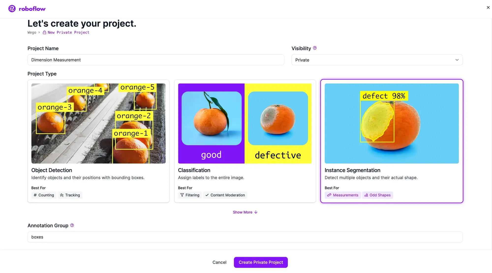
Choose a name for your project. Select “Instance Segmentation” as your project type. We are selecting this model type over "Object Detection" so we can measure items that are not perfectly boxes or are rotated. Once you have filled out the required fields, click “Create Project”.
Step #2: Upload & Label Data
To build the dimension inspection system, first label images of the object. The instance segmentation model will learn the outline of the object. We will extrapolate the width, length, and height from the polygon coordinates.
Collect 30-60 images of the different objects you want to identify. In this case we have collected images of:
- Ramen Box
- Hint Water Case
- Packaged Box
- Reference Object (only necessary for reference object approach)
Next, annotate your images to train the model to identify the ramen box and hint water case.
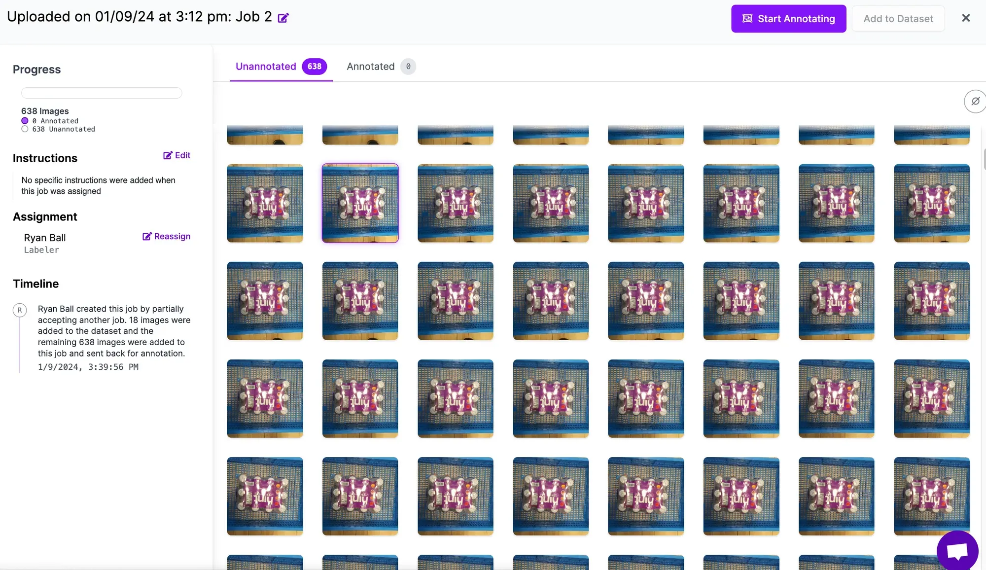
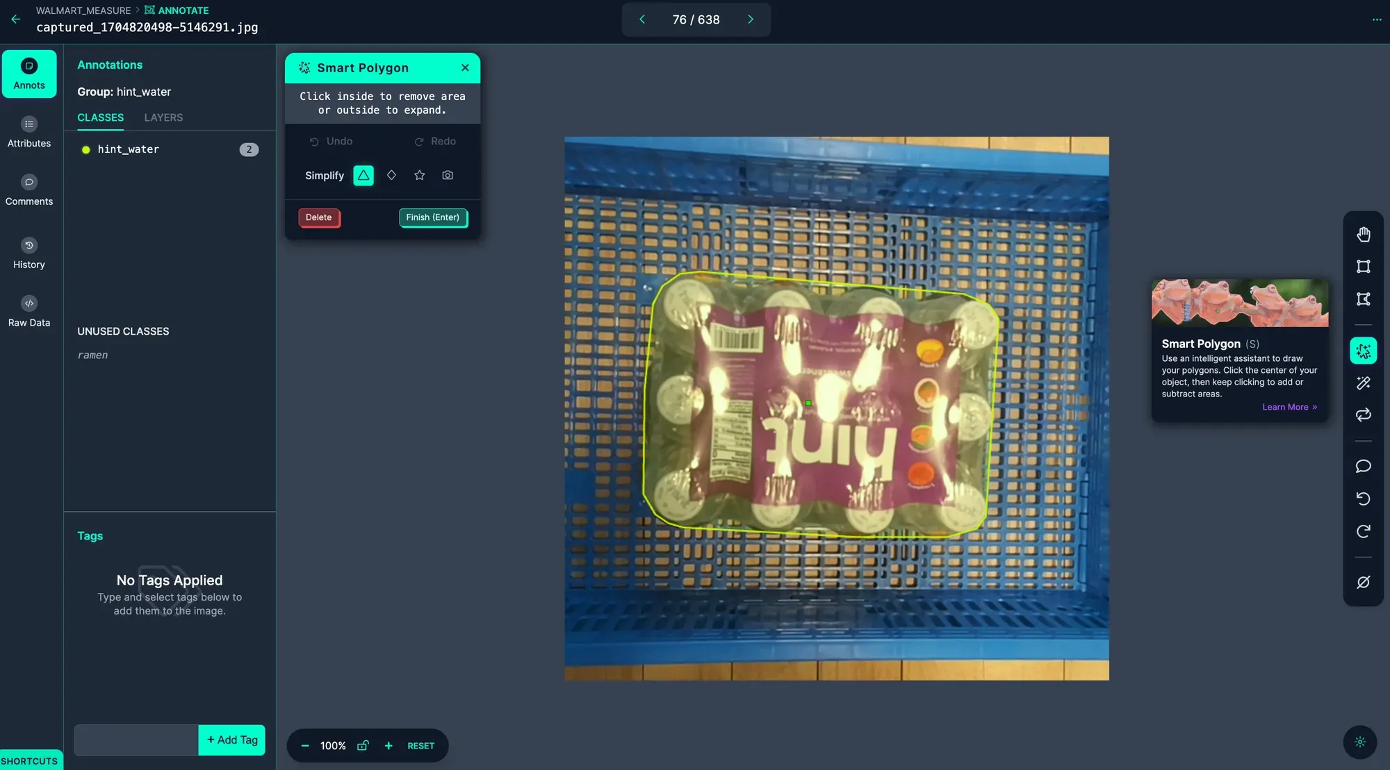
You can annotate your images with Roboflow Annotate. To get started, click Annotate in the left sidebar. Then, select an image to annotate. You will be taken to the labeling interface where you can label your data.
To speed up labeled, try Smart Polygon which uses an intelligent assistant to draw your polygons, oftentimes with a single click.
Step #3: Generate a Dataset Version and Train a Model
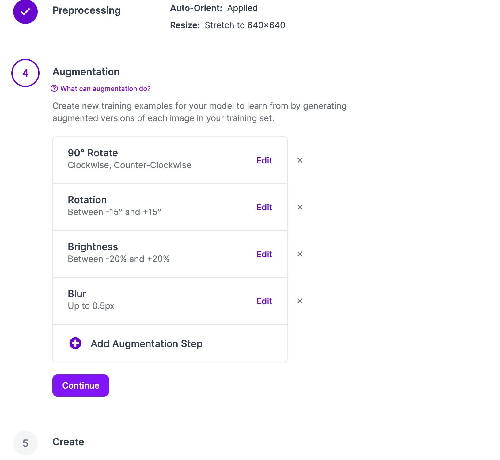
Now that your data is labeled and added to the dataset, you can generate a dataset version. A dataset version is a snapshot of your data on which you can train a model. You can apply preprocessing and augmentation steps to prepare your model for training and improve model performance, respectively.
To generate a dataset, click “Generate” in the sidebar. You will be taken to a page on which you can configure your dataset version.
Click the “Create” button under the “Generate” step at the bottom of the page to create your dataset version. With a dataset ready, you can train a model to detect ramen boxes and water boxes.
A pop up will appear in which you can configure your model training job. From this pop up, select “Fast” training. Then, select the option to train from the Microsoft COCO Checkpoint. Once you have configured your training job, an estimate will appear that shows roughly how long it should take to train your model.
You can monitor your training job in real time from your dataset page. Once your training job has been allocated to a machine, a graph will appear that shows the performance of your model as it trains.
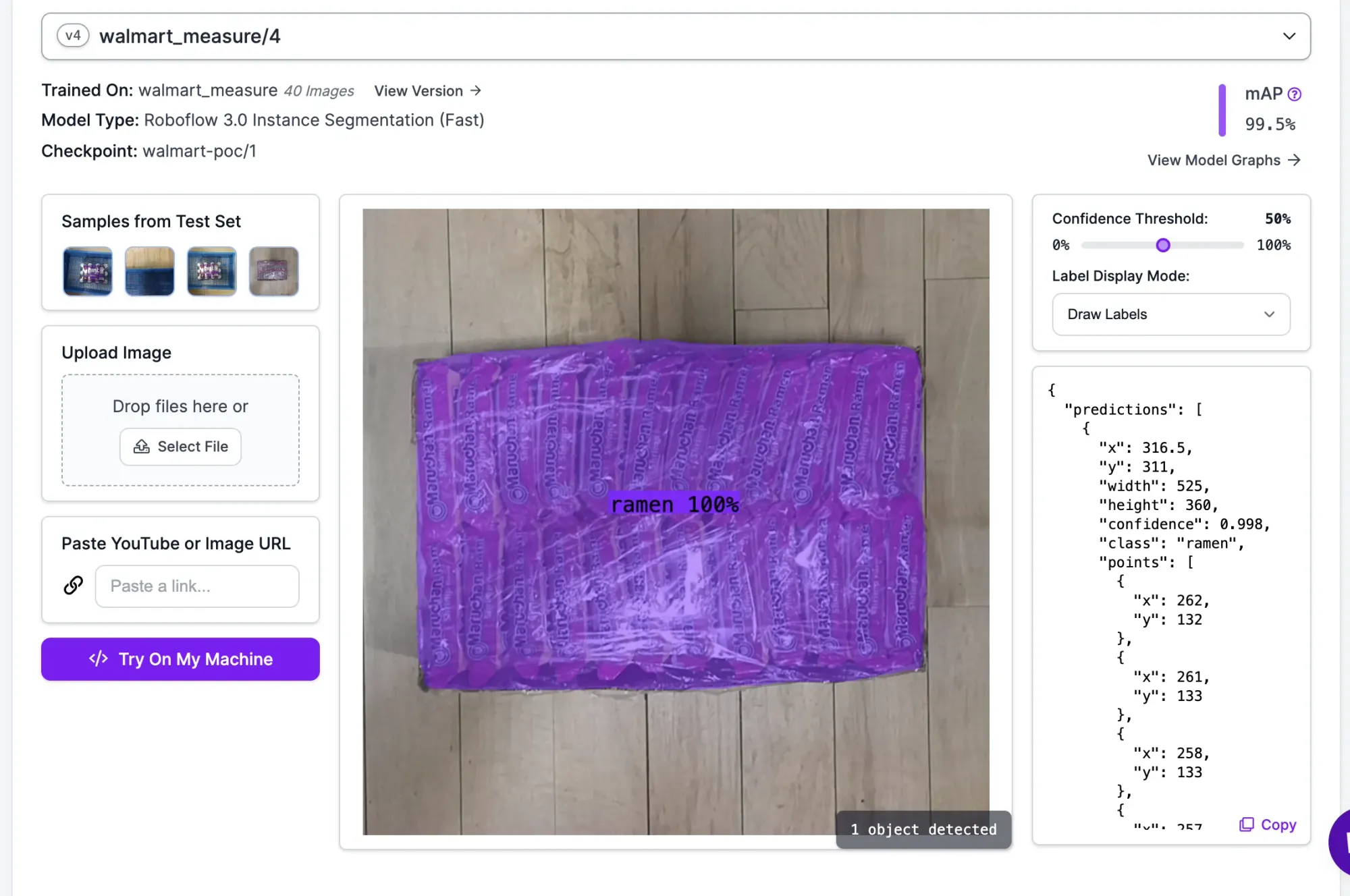
Our model successfully identified and segmented the ramen box, and is production ready given the 99.5% mean average precision (mAP) score.
Step #6 (Approach 1): Deploy Model with Reference Object to Measure Dimensions
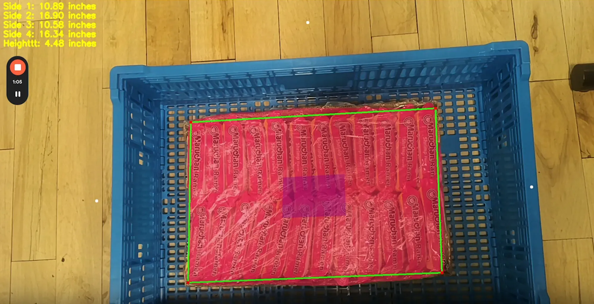
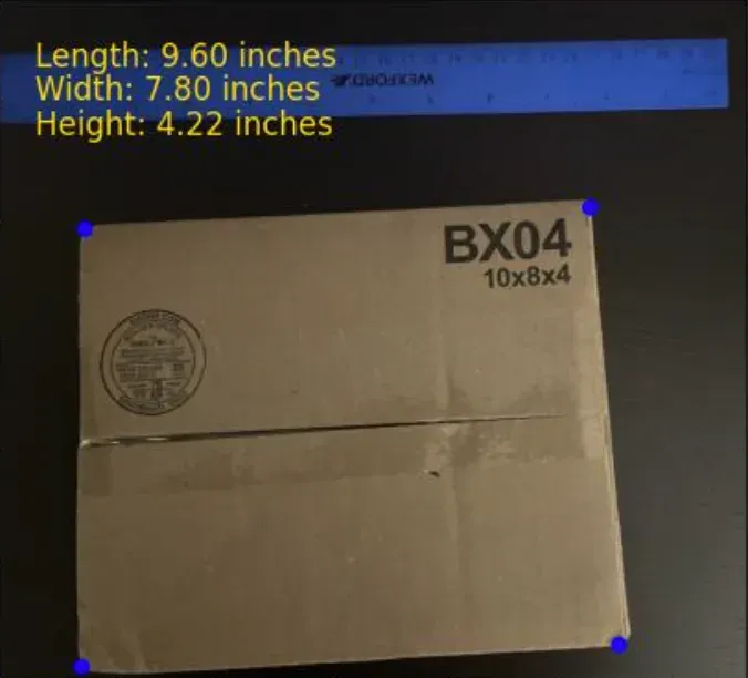
With a model ready, we can deploy our dimension inspection system. The first method involves using a reference object to obtain a real-world measurement that we then use as our inches to pixels conversion calculation
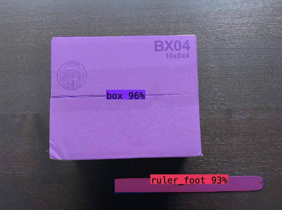
In this example, we are segmenting a ruler, and given the pixel length, diving by 12 to obtain a pixel:inches ratio. We then extrapolate the 4 corners of the box polygon to calculate the width and height. The same approach is taken from the side view to obtain the height.
Assuming you have a segmentation mask from a Roboflow model, here are the steps below:
# 4 corners of box derived from mask and polygon. Each corner is a x,y coordinate
corners = [top_left_corner,top_right_corner,bottom_right_corner,bottom_left_corner]

#calculate width in pixels
pixel_width = math.sqrt((top_right_corner["x"] - top_left_corner["x"]) ** 2 + (top_right_corner["y"] - top_left_corner["y"]) ** 2)

#calculate length in pixels
pixel_length = math.sqrt((top_left_corner["x"] - bottom_left_corner["x"]) ** 2 + (top_left_corner["y"] - bottom_left_corner["y"]) ** 2)

#calculate height in pixels
pixel_height = math.sqrt((bottom_point["y"] - top_point["y"]) ** 2)

#scale factor of pixels per inch. input pixel length of reference object derived from same calculation as above and divide by 12 inches
scale_factor = reference_object_length_pixels / 12

length_dimension = pixel_length/scale_factor
width_dimension = pixel_width/scale_factor
height_dimension = pixel_height/scale_factor
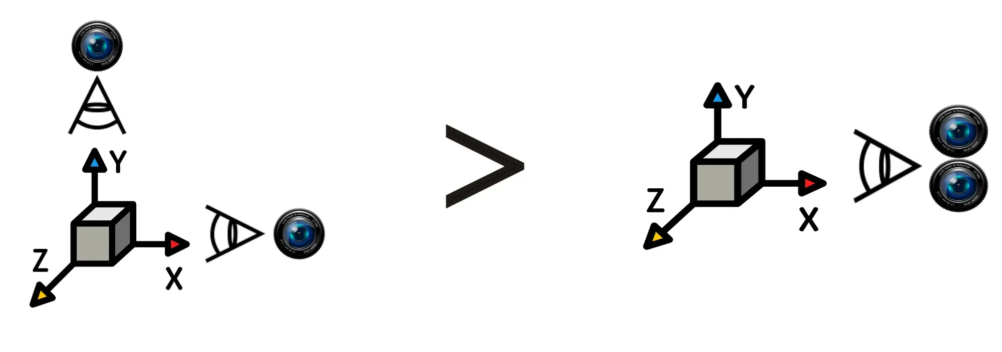
The 2 downsides with this approach are perception distortion and requiring two cameras. The reference object needs to be close to the object being measured – ideally on the object such as a QR code – otherwise the pixel:inches conversion is miscalculated. Two cameras would need to be set up to calculate all 3 dimensions.
Step #6 (Approach 2): Deploy Model with Depth Capabilities to Measure Dimensions
The second method involves using Luxonis Oak's stereo depth perception capabilities. Depth of objects is calculated by leveraging the stereo camera pair - left and right monocular cameras – and the VPU for disparity matching.
Here are the steps in calculating the width, length and height with Roboflow and a Luxonis Oak-D Pro:
- Run Roboflow inference on the camera stream to segment the object
- Calculate the lines and corners utilizing the polygon
- Pass the x,y coordinates of the 4 corners to the depth sensor to obtain depth from camera to top of box
- Select points on the ground to calculate depth from camera to ground
- Subtract the depth to ground from the depth to top of box to obtain height of box
- Leveraging the 4 corners of the box, calculate spatial x,y,z coordinates from the depth frame and each corner of the object.
- Use euclidian distance to calculate length of each side (natively in millimeters and divide by 25.4 to convert to inches)
Conclusion
You can use computer vision to estimate the dimensions of an object. In this guide, we discussed two ways you can estimate object dimensions:
- Using a reference object whose dimensions you know to calculate the dimensions of another object, and;
- Using a camera with depth capabilities.
Using this guide, you can build the logic you need to calculate dimensions for use in quality assurance systems, package sorting systems, and more.