The article below was contributed by Timothy Malche, an assistant professor in the Department of Computer Applications at Manipal University Jaipur.
Computer vision technology has revolutionized the way we handle important concerns such as wildfire detection and control in recent years.
Traditional fire detection technologies frequently rely on ground-based equipment or satellite imaging, which might have limitations in terms of accuracy, speed, and coverage
To address the rising hazard of wildfires, computer vision can be used. Computer vision can allow earlier detection of wildfires when deployed using across large swathes of forest that would be difficult for humans to monitor every day.
In this guide, we are going to show how to detect fires using aerial imagery. Let’s begin!
Aerial Fire Detection with Computer Vision
To build the system, we will need the following equipment and software:
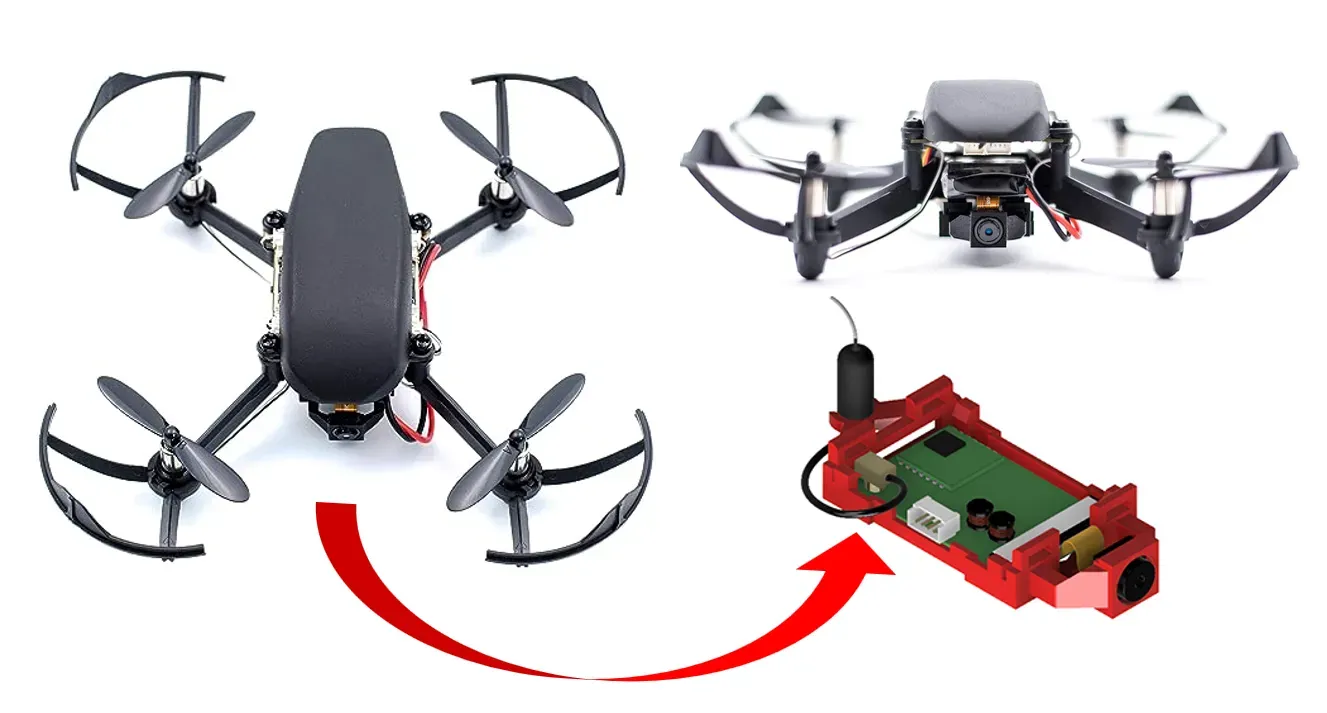
- A drone;
- A WiFi camera module, through which images can be collected;
- A Roboflow account, which we will use to label data, and;
- A Google Colab Notebook, which we will use to train a model.
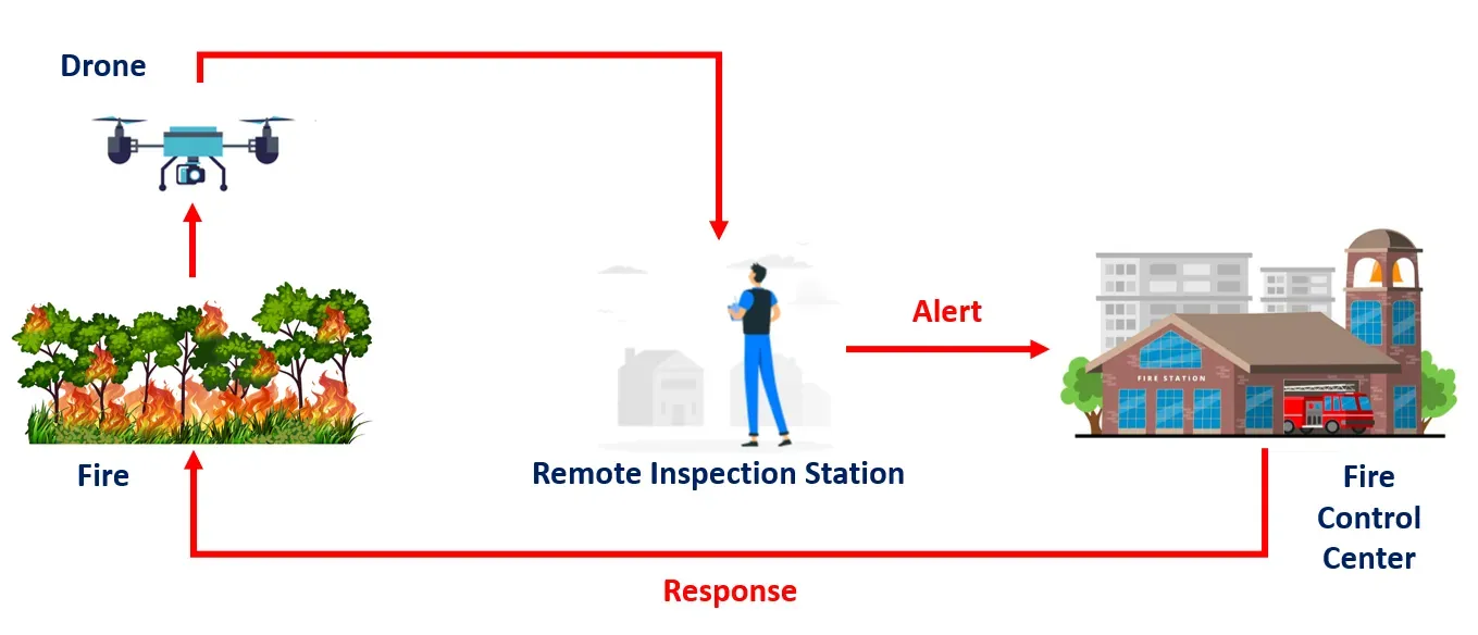
This project uses a drone equipped with a camera module for fire detection, involving remote monitoring and response through computer vision and coordination with a Fire Control Center. Here is a step-by-step description of this operation:
- Deployment of the Drone: The drone equipped with a camera module is deployed to the area that needs to be inspected for potential fire hazards. Drones are well-suited for this task as it can quickly cover large areas and can be accessed remotely.
- Remote Inspection Station: The drone is remotely controlled from an inspection station, typically operated by trained personnel.
- Computer Vision Analysis: The video stream or images captured by the drone's camera are sent to a computer vision model for analysis.
- Fire Detection: The computer vision model continuously processes the incoming data from the drone's camera. It looks for visual cues that indicate the presence of a fire, such as the appearance of flames, smoke, or changes in temperature patterns.
- Alert to Fire Control Center: Upon detecting a fire, the computer vision model sends an immediate alert to the Fire Control Center.
- Fire Control Center Response: The Fire Control Center receives the alert and assesses the information provided by the computer vision model. Based on this information, the center can make informed decisions about the appropriate response.
- Response Team Action: The response team, which is trained and equipped to handle firefighting and emergency situations, is dispatched to the location of the detected fire.
To build this project, we will follow these steps:
- Prepare a dataset
- Label a dataset and generate a snapshot for use in model training
- Train a model
- Test the model
Step #1: Dataset Preparation
The dataset for this project is obtained from The FLAME dataset: Aerial Imagery Pile burn detection using drones (UAVs), IEEE Dataport.
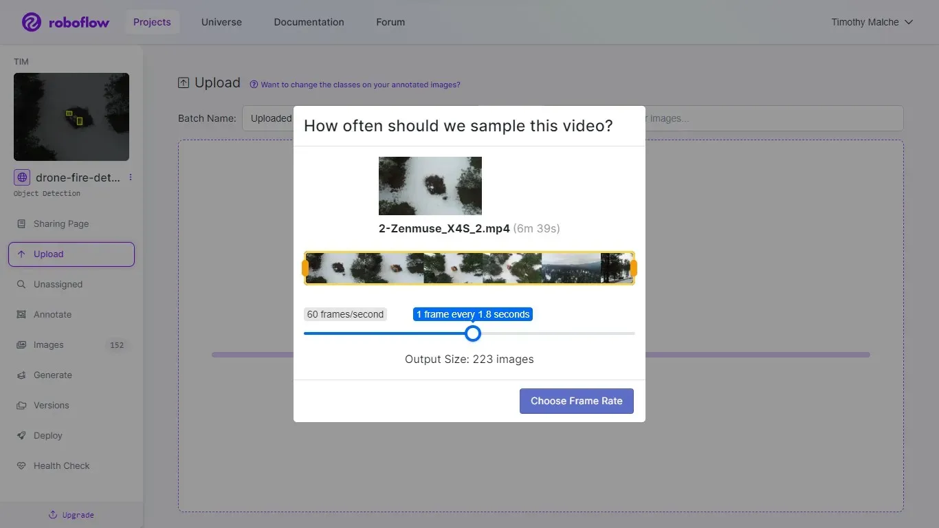
The dataset was first downloaded, then uploaded to our own Roboflow account. In the context of our fire detection project, the dataset is collected in video format (.mp4). Roboflow has a useful feature that enables users to effortlessly upload videos, subsequently automating the extraction of individual frames from the video and transforming them into distinct images.
Roboflow provides a user-friendly interface to specify the desired frame rate. This straightforward interface dictates how many images are to be generated from the video, streamlining the process considerably. A visual representation of this interface is depicted in the figure below. The utilization of Roboflow's tool greatly simplifies the complex task of gathering datasets and converting them into usable images.
Step #2: Dataset Labelling and Generation
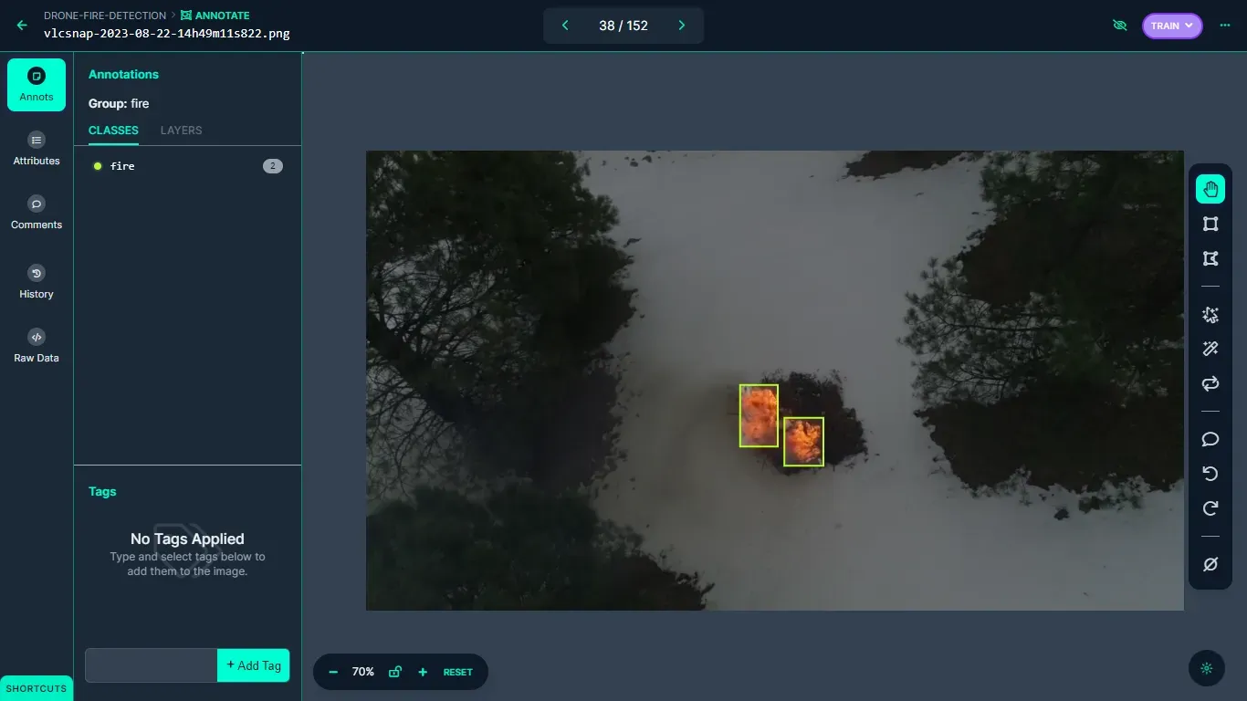
After images have been successfully uploaded, they can be annotated using Roboflow's annotation tool. In the context of this project, object detection bounding boxes are used to label these images. The label fire is used to annotate all occurrences of fire within the dataset. The labeling process is a critical step in preparing the dataset for training, as well as enabling the computer vision model to accurately identify and classify instances of fire within the images.
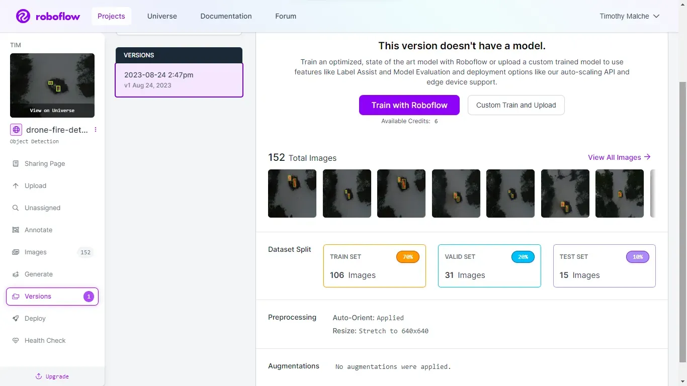
Once all the images in the dataset have been labeled with the 'Fire' class, the dataset version is generated. The settings used to generate this dataset version is illustrated in the following image.
Step #3: Training the Model
Following the annotation process, we proceeded to train the Ultralytics YOLOv8 object detection model using a Jupyter Notebook. You can easily follow each step of this process by accessing and downloading the notebook through this link. The dataset necessary for training the YOLOv8 model for this project, can be acquired using the provided code snippet below.
from roboflow import Roboflow
rf = Roboflow(api_key="YOUR_API_KEY")
project = rf.workspace("YOUR_WORKSPACE").project("drone-fire-detection-byija")
dataset = project.version(1).download("yolov8")
Learn how to retrieve your Roboflow API key.
Once the dataset is successfully obtained from Roboflow universe, the model training process can be initiated using the following command.
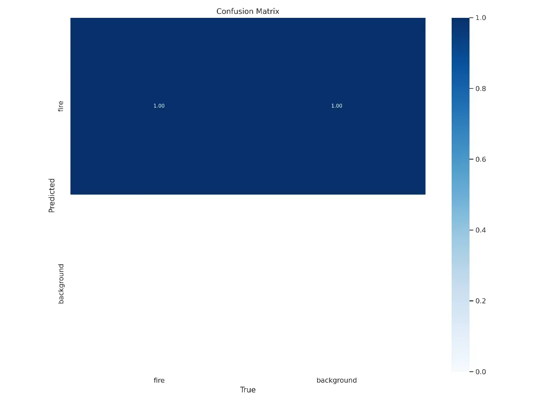
yolo task=detect mode=train model=yolov8m.pt data={dataset.location}/data.yaml epochs=50 imgsz=800 plots=TrueBelow, we can see how our model performs at detecting the `Fire` class. Our model achieves a 0.95% recall rate, a 0.99% mAP50 score, and a 0.63% mAP50-95.
After the successful training of the YOLOv8 model, the trained weights are then deployed back to Roboflow. This deployment process renders the trained model accessible for inference through Roboflow's hosted inference API.
Step #4: Deploying and Testing the Model
Roboflow provides a user-friendly interface for uploading and preparing the trained model for immediate use. You can deploy the model from Python code directly to the Roboflow platform, or on a device with https://github.com/roboflow/inference. But in this guide, we will load our model directly in a notebook for testing.
We will export the trained YOLOv8 model into a .pth file and subsequently incorporate it into a Python script for inferencing purposes. This section illustrates how Roboflow's Supervision can be employed to evaluate the performance of the trained model.
To obtain the weights of the trained YOLOv8 model, you can use the provided code snippet for downloading.
# Export your model weights for future use

from google.colab import files
files.download('/content/runs/detect/train/weights/best.pt')
Running Inference on Images
The "best.pt" weight file will be utilized in conjunction with Supervision to create a custom detector. Initially, we will use Supervision to execute inference on an image. You can refer to this notebook for a step-by-step walkthrough.
The test image can be specified with the following code:
import cv2

IMAGE_PATH = "/content/fire.png"
image = cv2.imread(IMAGE_PATH)
Following that, we need to load our custom model and perform inference on the specified image using the custom model.
from ultralytics import YOLO
import supervision as sv

model = YOLO('best.pt')
result = model(image, verbose=False)[0]
detections = sv.Detections.from_ultralytics(result)
The supervision BoxAnnotator is used to label objects within the image and the plot_image() function to showcase the detection outcomes.
box_annotator = sv.BoxAnnotator()
labels = [
f"{model.model.names[class_id]} {confidence:.2f}"
for class_id, confidence
in zip(detections.class_id, detections.confidence)
]
annotated_image = box_annotator.annotate(image.copy(), detections=detections, labels=labels)
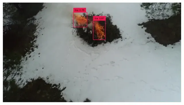
sv.plot_image(image=annotated_image, size=(8, 8))The above code takes the results of object detection from a custom model, generates labels for each detected object, annotates the input image with bounding boxes and labels, and then displays the annotated image for visualization. The following shows the output generated after running the above code:
Running Inference on Video
Next, we utilize Supervision for performing inference on a captured video. To achieve this, both the source video which we have captured and target video that we wish to generate as output.
SOURCE_VIDEO_PATH = f"{HOME}/fire.mp4"
TARGET_VIDEO_PATH = f"{HOME}/fire_result.mp4"
In our video inference application, we will incorporate BYTETrack, a multi-object tracking framework. BYTETrack plays a crucial role in enhancing tracking consistency by preserving relevant bounding boxes that might otherwise be discarded due to low confidence scores, often caused by occlusion or appearance changes. You can refer to this accompanying notebook for guidance throughout this process.
After installing YOLOv8, download BYTETrack and install it with the following command:
%cd {HOME}
!git clone https://github.com/ifzhang/ByteTrack.git
%cd {HOME}/ByteTrack

# workaround related to https://github.com/roboflow/notebooks/issues/80
!sed -i 's/onnx==1.8.1/onnx==1.9.0/g' requirements.txt
!pip3 install -q -r requirements.txt
!python3 setup.py -q develop
!pip install -q cython_bbox
!pip install -q onemetric
# workaround related to https://github.com/roboflow/notebooks/issues/112 and https://github.com/roboflow/notebooks/issues/106
!pip install -q loguru lap thop
We also need to install supervision:
!pip install supervision==0.1.0Next, import the dependencies for use in your project:
from IPython import display
display.clear_output()

import sys
sys.path.append(f"{HOME}/ByteTrack")

import yolox
print("yolox.__version__:", yolox.__version__)

from yolox.tracker.byte_tracker import BYTETracker, STrack
from onemetric.cv.utils.iou import box_iou_batch
from dataclasses import dataclass

@dataclass(frozen=True)
class BYTETrackerArgs:
    track_thresh: float = 0.25
    track_buffer: int = 30
    match_thresh: float = 0.8
    aspect_ratio_thresh: float = 3.0
    min_box_area: float = 1.0
    mot20: bool = False

from IPython import display
display.clear_output()

import supervision
print("supervision.__version__:", supervision.__version__)

from supervision.draw.color import ColorPalette
from supervision.geometry.dataclasses import Point
from supervision.video.dataclasses import VideoInfo
from supervision.video.source import get_video_frames_generator
from supervision.video.sink import VideoSink
from supervision.notebook.utils import show_frame_in_notebook
from supervision.tools.detections import Detections, BoxAnnotator
We can use the packages above to build an object detection and tracking pipeline, where detections from an object detection model are matched with existing tracked objects. The result is a list of tracker IDs associated with each detection. This is a critical step in multi-object tracking systems.
The next step involves loading our custom-trained model, specifically designed for detecting instances of fire. We will accomplish this by loading the model from the "best.pt" file.
MODEL = "/content/best.pt"
from ultralytics import YOLO

model = YOLO(MODEL)
model.fuse()
Define the classes utilized in the model. In our case, there is only one class.
# dict maping class_id to class_name
CLASS_NAMES_DICT = ['fire'] #model.model.names
# class_ids of interest
CLASS_ID = [0]
Finally, we can run inference on a video.
The following code processes the frames from a source video specified by SOURCE_VIDEO_PATH and are processed using a custom object detection model and potentially tracked using the BYTETracker. Annotations are then added to the frames, and the processed frames are written to a new video file specified by TARGET_VIDEO_PATH.
from tqdm.notebook import tqdm

# create BYTETracker instance
byte_tracker = BYTETracker(BYTETrackerArgs())
# create VideoInfo instance
video_info = VideoInfo.from_video_path(SOURCE_VIDEO_PATH)
# create frame generator
generator = get_video_frames_generator(SOURCE_VIDEO_PATH)
# create instance of BoxAnnotator
box_annotator = BoxAnnotator(color=ColorPalette(), thickness=2, text_thickness=2, text_scale=1)

# open target video file
with VideoSink(TARGET_VIDEO_PATH, video_info) as sink:
    # loop over video frames
    for frame in tqdm(generator, total=video_info.total_frames):
    # model prediction on single frame and conversion to supervision Detections
        results = model(frame)
        detections = Detections(
        xyxy=results[0].boxes.xyxy.cpu().numpy(),
        confidence=results[0].boxes.conf.cpu().numpy(),
        class_id=results[0].boxes.cls.cpu().numpy().astype(int)
        )
        # format custom labels
        labels = [
        f"{CLASS_NAMES_DICT[class_id]} {confidence:0.2f}"
        for _, confidence, class_id, tracker_id
        in detections
        ]
        # annotate and display frame
        frame = box_annotator.annotate(frame=frame, detections=detections, labels=labels)
        sink.write_frame(frame)
In the code given above, an instance of the BYTETracker class is created. Then, a VideoInfo instance is created by extracting frames from a source video located at SOURCE_VIDEO_PATH. The next line sets up a frame generator using a function called get_video_frames_generator. This generator is likely used to iterate through frames of the source video one by one.
We also created an instance of BoxAnnotator. This object is used for annotating frames, potentially adding bounding boxes and text to highlight objects or features in the video frames.
Next, we create an instance of the VideoSink class. TARGET_VIDEO_PATH is the path where the processed video will be saved, and video_info contains information about the video to be saved. The with statement suggests that this object handles the writing of processed frames to the target video file.
A loop iterates through the frames of the source video and visually tracks the progress of frame processing. For each frame, our computer vision model is applied to retrieve predictions of the location of fire. The frame is passed as input to the model, and the results are stored. These results include information about detected objects, and its confidence scores.
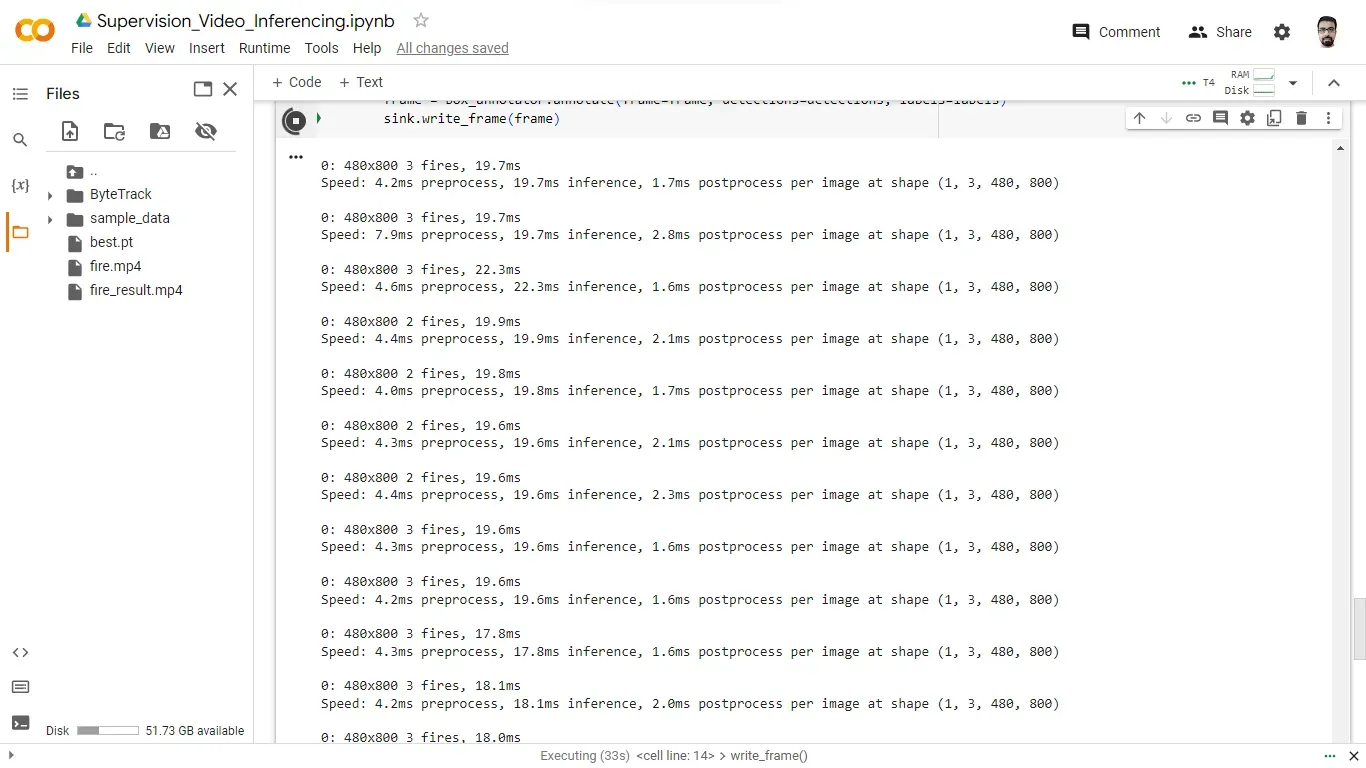
While the above code is running and writing the results file, the program displays the number of objects detected in each frame that is being created.
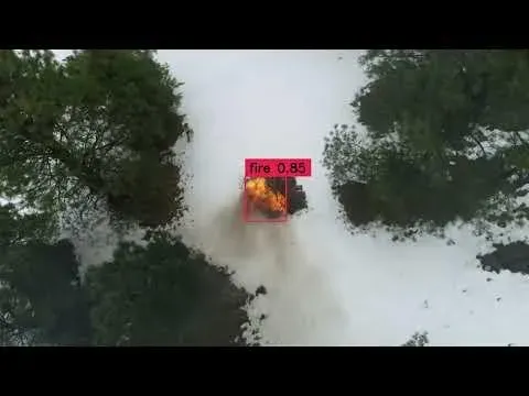
The resultant video below, show the detected class with bounding box.
Conclusion
In this project, we developed a fire detection system using computer vision techniques and a custom-trained YOLOv8 model. This system is designed to identify instances of fire in both images and video streams, enabling early detection and rapid response to mitigate potential disasters.
Through the described project-building steps in this blog, a fire detection system can be created that leverages computer vision, object detection, and tracking techniques. This system contributes to early fire detection, providing valuable time for response teams to take necessary actions, ultimately improving safety and reducing the impact of wildfires.
All code for this project is available at github. The dataset used for this project is available on Roboflow Universe.